blog

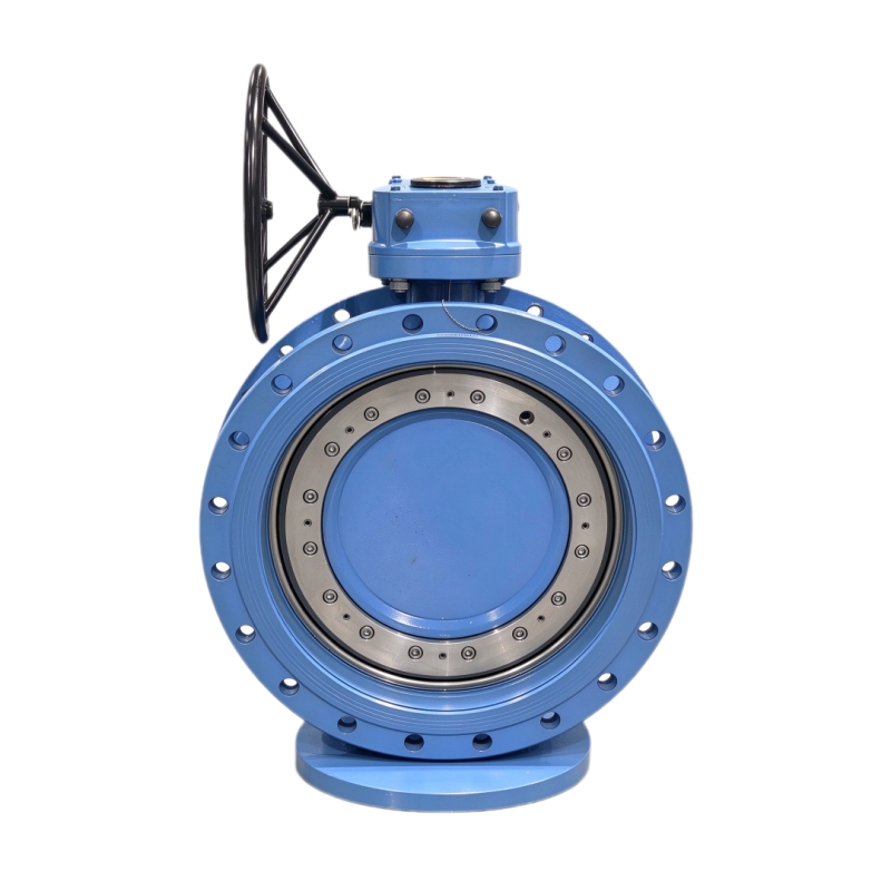
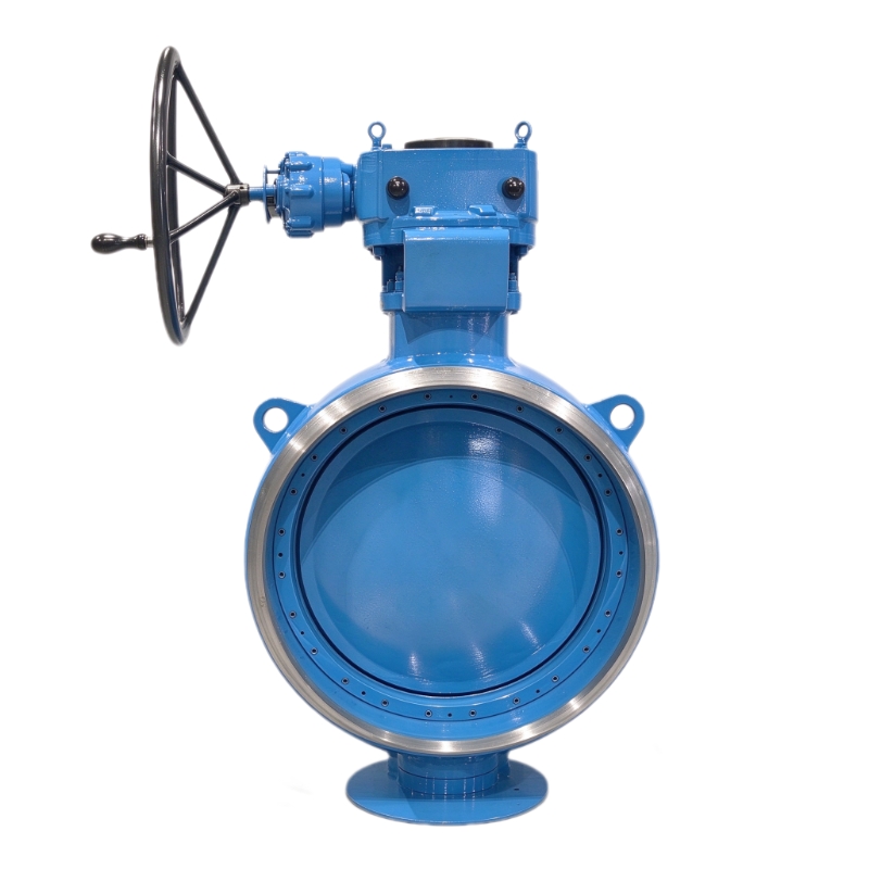
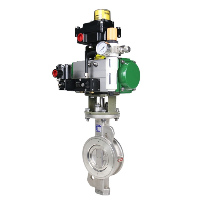
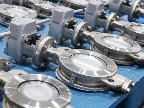
  • GEKO Valves: Redefining High-Performance Regulation of Triple-Offset Butterfly Valves with Nine Core Technologies
    GEKO Valves: Redefining High-Performance Regulation of Triple-Offset Butterfly Valves with Nine Core Technologies
    Jul 01, 2026
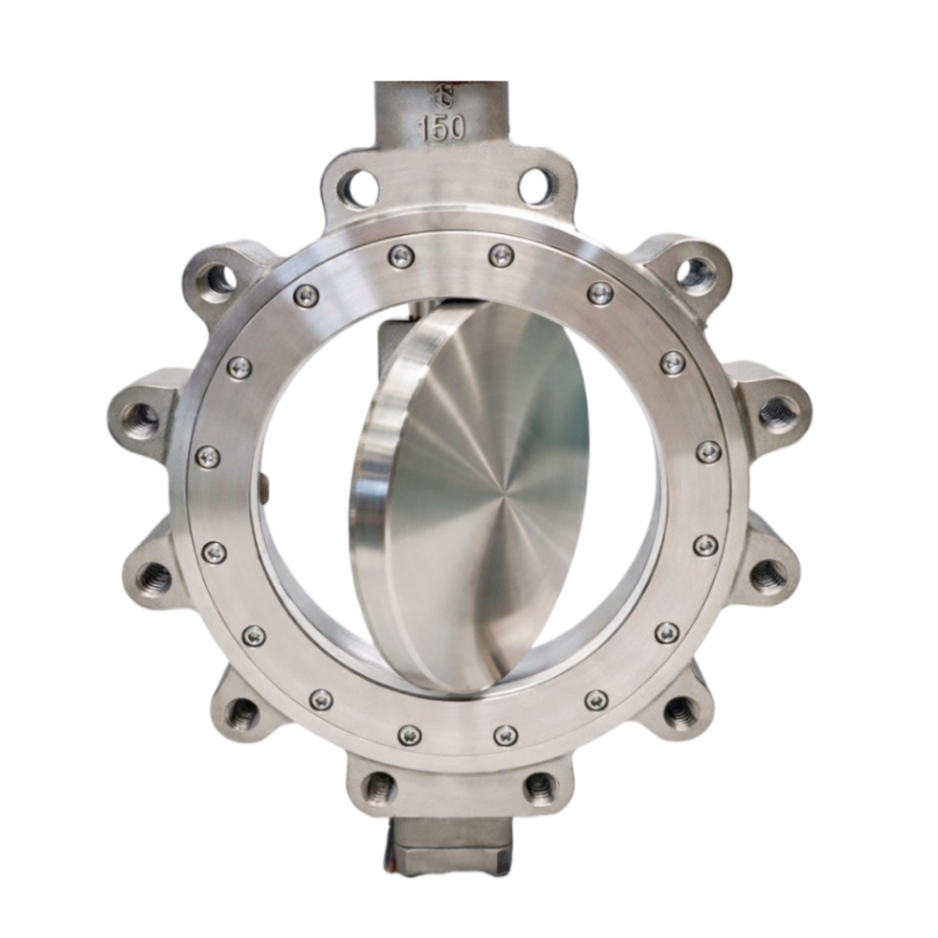
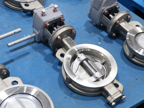
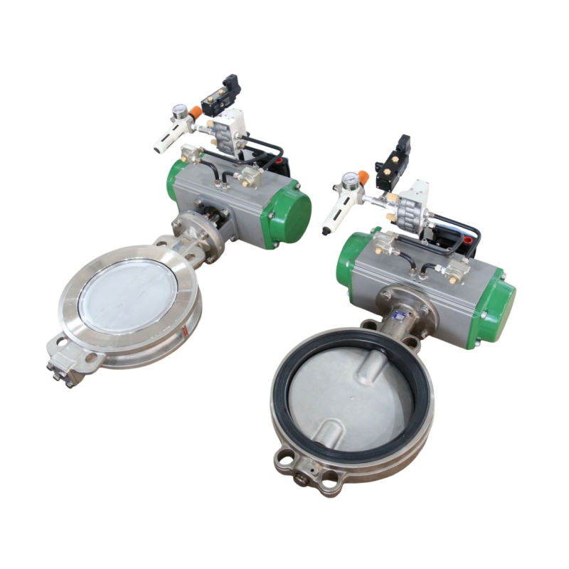
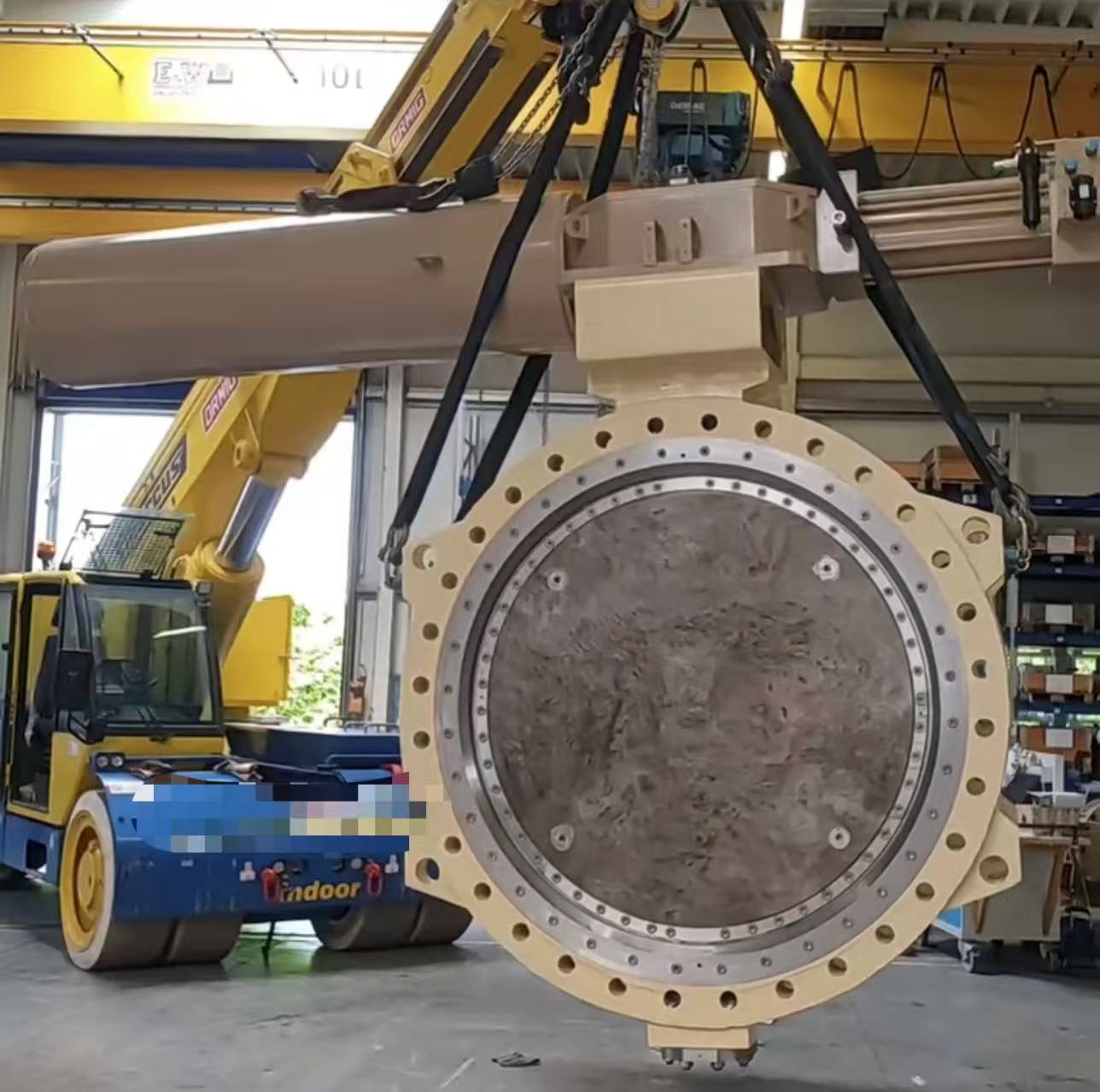
    In demanding industrial control applications, achieving "high-performance regulation" with triple-offset butterfly valves requires simultaneously overcoming three major challenges: small-opening turbulence, high-differential-pressure stability, and long-term dynamic rigidity. GEKO Fluid Control GmbH, drawing on deep expertise in fluid dynamics and precision manufacturing, has elevated the triple-offset butterfly valve from a reliable shut-off device to a precision control instrument through nine key technological innovations.   Fluid Optimization – Suppressing Disturbances at the Source Streamlined large-spherical-profile disc design optimizes the pressure distribution on the upstream face, effectively reducing vortex fluctuations at small openings.   Optimized cone half-angle and pivot radius minimize friction dead zones and enable rapid sealing-face disengagement, enhancing response sensitivity at micro-openings.   Flow Path Innovation – Balancing Pressure Reduction and Linear Control   Outlet half-orifice plate design reduces downstream vortices and lowers pressure drop, significantly improving regulation stability under high differential pressure.   Valve seat flow-guide groove design converts the inherent quick-opening characteristic into a smooth equal-percentage flow characteristic, eliminating flow surges and ensuring uniform regulation gain across the full travel range.   Severe-Service Engineering – Specialized for High Differential Pressure and Low Flow   Flow-to-open direction as standard (for blow-down, FO, and similar applications) minimizes dynamic torque fluctuations and enhances stem stability.   40–60% variable cavity reduction design in the valve seat increases flow velocity at small openings, overcoming the traditional limitation of poor controllability at low openings.   Reliability Assurance – From Torque Matching to Structural Integrity   Precise dynamic torque matching with actuator output at every opening degree ensures reliable driving force across the entire stroke.   Full-key, non-pin stem-to-disc connection provides greater load-bearing area and shear strength, ensuring rigidity and fatigue resistance under high-frequency modulation.   Anti-loosening design for sealing-face compression screws withstands high-velocity fluid impact, guaranteeing consistent sealing preload during long-term dynamic regulation.   Conclusion Through the synergistic integration of these nine precision-engineered features, GEKO has fundamentally broken the traditional perception that triple-offset butterfly valves are "only for shut-off." At GEKO, high-performance regulation represents the optimal convergence of fluid dynamics, materials science, and engineering excellence.  
    ĐỌC THÊM
  • GEKO Valves — Providing Precise and Reliable Control Solutions for Turbine Safety
    GEKO Valves — Providing Precise and Reliable Control Solutions for Turbine Safety
    Jun 10, 2026
    In steam turbine operation systems, VV valves, BDV valves, and RFV valves are all auxiliary protection and start-up control valves. Their names are similar, and their functions are highly related. Field operators are prone to conceptual confusion, functional misjudgment, and operational errors. This article systematically clarifies the core definitions, structural principles, interlock logic, operational requirements, and key differences of these three types of valves, based on turbine design principles, unit start-stop logic, and field operation standards, providing professional technical reference for operation, maintenance, commissioning, and overhaul. GEKO Valves, with their high-precision pneumatic control technology and rigorous industrial validation, have become a trusted brand in the manufacturing and system integration of these critical valves.     I. Core Valve Definitions & Structural Working Principles (i) VV Valve (Vent Valve — HP Exhaust Vent Valve) Located on the high-pressure (HP) exhaust pipeline, this special vent and pressure relief valve leads directly to the condenser and drain flash tank. It is mainly used in intermediate-pressure (IP) start-up units to solve windage overheating issues in the HP cylinder under low load or no-inlet steam conditions, while also providing rapid pressure relief after tripping to prevent overspeed.     During IP start-up or low-load operation, the HP cylinder has little or no inlet steam, and the HP exhaust non-return valve remains closed. The blades inside the HP cylinder generate significant heat due to air friction (windage), which can easily cause overheating damage to the HP blades and casing. After a turbine trip, residual steam in the HP cylinder can leak into the vacuum state of the IP cylinder through HP-IP shaft seals, creating a risk of rotor overspeed. The VV valve quickly evacuates residual steam from the HP cylinder to avoid these risks.   It uses a pneumatically controlled, air-to-close design, consisting of an air supply, cylinder, spring assembly, and solenoid valve. GEKO Valves features an optimized high-temperature spring assembly and low-friction cylinder in this product, ensuring reliable valve opening under air failure conditions, with solenoid valve response time ≤0.5 seconds, significantly improving the timeliness of windage overheating protection.     (ii) BDV Valve (Break Drain Valve — Turbine Emergency Drain Valve) An emergency pressure relief protection valve specifically designed for combined HP-IP turbines, also known as the HP-IP shaft seal residual steam dump valve. Its core function is to quickly discharge steam that leaks past shaft seals under unit load rejection or trip conditions, eliminating the risk of turbine overspeed.     During load rejection or emergency trip of combined HP-IP units, residual steam in the HP cylinder and HP inlet pipes can leak through the HP-IP shaft seal gaps into the IP and low-pressure (LP) cylinders, creating additional driving force on the rotor. If seal teeth are worn or gaps increase, the amount of leaking steam increases, significantly raising the risk of overspeed. The BDV valve directs this residual shaft seal steam directly into the condenser, quickly releasing pressure and completely blocking the overspeed path.   It uses an electromagnetic-pneumatic linkage structure, controlled by the stroke signal of the IP control valve oil servo. GEKO Valves' BDV product adopts a redundant dual-solenoid valve design with a highly reliable pneumatic control circuit, achieving full-stroke action within 0.3 seconds after the oil servo stroke signal is triggered, effectively preventing the escalation of overspeed accidents.   (iii) RFV Valve (Reheat Warm-up Valve — HP Cylinder Reverse Warming Valve) A dedicated warm-up control valve for cold starts, used to pre-heat the HP cylinder before cold start, eliminating casing temperature differences, reducing thermal stress, and ensuring the unit meets parameters for rolling.   During a cold start, the HP cylinder casing and internal components are at very low temperatures. Directly introducing steam for rolling would create huge thermal stress, leading to casing deformation, metal cracks, and excessive shaft vibration. The RFV valve introduces auxiliary steam upstream of the HP exhaust non-return valve. The steam flows evenly through the HP cylinder and is discharged through HP inner casing drains and HP inlet pipe drains, gradually raising the casing temperature to achieve uniform warm-up.   GEKO Valves has specifically developed an RFV valve with linear regulation characteristics for these operating conditions. It uses a low-leakage seal design and anti-seize valve core, allowing precise temperature control under low flow and low differential pressure conditions, with warming rate control accuracy of ±1.5°C/h, significantly outperforming conventional products.     II. Valve Interlock Control Logic VV Valve Interlock Logic Close Interlock: Receives stroke switch signals from the four HP control valve pre-pilot valves. When all four pre-pilot valves are fully open and unit steam flow reaches 0.5% BMCR, the VV valve automatically closes. 1 minute after unit grid connection, the HP exhaust non-return valve opens, and the VV valve closes via interlock.   Open Interlock: Automatically opens during initial IP start-up and low-load windage conditions. Immediately opens via interlock after turbine trip to quickly evacuate residual HP steam.   BDV Valve Interlock Logic Close Interlock: Controlled by IP control valve oil servo stroke. When oil servo stroke ≥30mm, or when the left/right IP control valve opening reaches 15%~16% (corresponding to ~5% flow command) and the pre-pilot valve is fully open, the BDV valve automatically closes.   Open Interlock: Automatically opens when IP control valve oil servo stroke <30mm. Quickly opens via interlock under turbine trip and load rejection conditions to discharge shaft seal steam.   Pre-Pilot Valve Function Note The turbine control valve pre-pilot valve is an auxiliary valve for the main valve disc. Before the main valve disc opens, the pre-pilot valve opens first, allowing new steam to flow through the pre-pilot passage, balancing the pressure differential across the main valve. This significantly reduces the force required to open the main valve, reduces the oil servo load, and avoids difficult or stuck valve opening.   III. Field Operation & Operational Requirements Pre-Start Check: Before unit start-up and rolling, the open/close status of VV and BDV valves must be confirmed both locally and via DCS. Never start the unit with abnormal valve status.   IP Start-Up Operation: Before start-up, confirm VV and BDV valves are open. If a manual isolation valve is installed upstream of the VV valve, check that it is fully open to avoid false action due to abnormal instrument air pressure or solenoid valve failure.   Post-Valve Transfer: After completing valve transfer following IP start-up, double-check (on DEH screen and locally) that the VV valve is fully closed to prevent steam leakage or pressure abnormalities after HP cylinder admission.   Unstable Conditions: During initial start-up, commissioning, or unstable operation, do not close the manual isolation valve upstream of the VV valve, leaving an emergency path available. After stable operation, close the manual isolation valve promptly.   Post-Trip Emergency: Immediately after a trip during operation, arrange personnel to locally check and open the manual isolation valve upstream of the VV valve, while verifying BDV valve position via DCS and locally, ensuring both valves open correctly for rapid pressure relief.   Normal Start-Stop: Monitor BDV valve position feedback in real-time after the interceptor valve opens during start-up and after a trip to ensure reliable interlock action.   Cold Start Warm-Up: Before rolling during a cold start, open the RFV valve for HP cylinder reverse warming. Monitor drain paths and casing temperature rise rate. Close the RFV valve after warm-up and proceed with normal start-up.   GEKO Valve Note: Accurate valve status feedback is critical in the above operations. GEKO valves come standard with high-precision limit switches and 4-20mA position transmitters, seamlessly integrating with DCS systems to significantly reduce misjudgment risks.     IV. Key Differences & Functions of the Three Valves     Valve Core Function Control Signal Source Main Application VV Valve HP cylinder venting, addresses windage overheating, auxiliary pressure relief after trip HP control valve pre-pilot stroke, steam flow, trip signal Initial IP start-up, low-load operation, turbine trip BDV Valve Discharges shaft seal steam, core overspeed prevention IP control valve oil servo stroke, IP valve opening signal Load rejection, emergency trip, IP valve not fully open RFV Valve HP cylinder cold pre-warming, reduces thermal stress Manual control + warm-up sequence Before turbine cold start     Key Functional Distinction:   VV Valve: Focuses on daily windage overheating protection; auxiliary pressure relief after trip.   BDV Valve: Core overspeed protection valve, specifically targeting shaft seal steam leakage.   RFV Valve: Only used for cold start warm-up, no accident protection function. These three functions are not interchangeable.   GEKO Valves has developed dedicated valve series for each of these three needs, with differentiated designs from material selection (e.g., high-temperature alloy seat for VV valve), sealing structure (metal hard seal + flexible graphite for BDV valve), to actuator configuration (smart positioner optional for RFV valve), ensuring the right valve for each application.   V. Shaft Seal & Stem Leakage System Summary (Typical Plant Configuration) Main Stop Valve: 1st stage leakage → sealing steam header, 2nd stage leakage → sealing steam return header   HP Control Valve: 1st stage leakage → reheater, 2nd stage leakage → sealing steam header   IP Interceptor Valve: Only 1st stage leakage → sealing steam header   BDV Valve: 1st stage leakage → reheater, 2nd stage leakage → sealing steam header   VV Valve: 1st stage leakage → 4th extraction pipe, 2nd stage leakage → sealing steam header   HP Shaft Seal: 3rd stage leakage → 4th extraction pipe   In the above system, GEKO Valves provides matching shaft seal leak control valves and stop valves, ensuring stable leak-off pressures, reducing steam waste, and improving unit thermal economy.   VI. Core Technical Q&A 1. What are the core functions of the VV valve and BDV valve? VV Valve: During IP start-up and low-load operation, connects the HP cylinder to condenser vacuum, evacuating air from the cylinder to reduce windage heating and avoid HP blade/casing overheating. After a trip, quickly releases residual HP steam, assisting in overspeed prevention.   BDV Valve: During a trip or load rejection, quickly discharges steam that leaks from the high-pressure side through shaft seal gaps into the IP cylinder, directly cutting off additional driving force. It is a critical overspeed prevention valve.   2. Why choose GEKO valves for these critical applications? GEKO Valves has over 20 years of experience in developing specialized valves for steam turbines. Our products hold ISO 15848-1 fugitive emission certification and SIL2 functional safety certification. The VV, BDV, and RFV series have accumulated over 100,000 hours of safe operation in multiple ultra-supercritical and subcritical units worldwide, with an action success rate exceeding 99.96%. GEKO provides full-cycle technical support — from valve selection and interlock logic optimization to field commissioning — helping power plants reduce unplanned outage risks caused by valve misoperation or failure to operate.     Conclusion VV, BDV, and RFV valves each play a distinct, non-interchangeable role in turbine start-up and protection. Operating and maintenance personnel must not only master their working principles and interlock logic but also pay attention to the quality and reliability of the valves themselves. GEKO Valves, with solid technical expertise and extensive field experience, provides high-performance, high-reliability products and complete solutions for these three valve types, helping power plants achieve safer and more efficient operation.   For specific valve selection and interlock settings, please refer to the OEM design drawings and actual site conditions. GEKO Valves offers tailored technical consultation.
    ĐỌC THÊM
  • Geko Fluid Control Technology (Changzhou) Wins Valve Supply Bid from CSSC No.703 Research Institute
    Geko Fluid Control Technology (Changzhou) Wins Valve Supply Bid from CSSC No.703 Research Institute
    Jun 08, 2026
    Geko Fluid Control Technology (Changzhou) Co., Ltd. has successfully won a competitive bidding project from the No.703 Research Institute of China State Shipbuilding Corporation Limited (CSSC). The bid award was officially announced on May 7, 2026, under project number TPJG202605070010.     The scope of supply includes ball valves, butterfly valves, globe valves, and check valves – marking an important milestone for Geko in the marine and ocean engineering sector.   German Engineering, Deep Roots in China   Geko Fluid Control Technology (Changzhou) is the core Chinese subsidiary of GEKO, a well-known European control valve manufacturer with over 60 years of history. GEKO is recognized for high-pressure and extreme-temperature resistance, with some products rated up to 60,000 psi and temperature ranges from -252°C to 649°C.     Founded in 2008 with a registered capital of 50.1 million RMB, the Chinese company is headquartered in Changzhou, Jiangsu Province. Its new factory, launched in 2022, has an annual production capacity of 120,000 units, manufacturing pneumatic/electric ball valves, butterfly valves, control valves, gate valves, globe valves, check valves, actuators, positioners, and limit switches.   Proven Track Record: National Flagship Projects     With robust product quality, Geko has participated in multiple prestigious national projects:   High-speed rail: Custom valves for CRRC high-speed train sets, passing 300,000 km road tests. Ultra-high voltage (UHV) grids: Electric explosion-proof ball valves with a 40-year design life for State Grid. Aerospace & nuclear power: Supply to rocket launch bases, Pakistan nuclear power projects, and multiple Belt and Road international projects. Domestic nuclear power: Products applied in major nuclear projects including the “Linglong One” small modular reactor. Strategic Focus: Hydrogen & New Energy   GEKO’s global strategic priority is the hydrogen energy sector, covering the entire value chain of production, storage, transport, and refueling. Core technologies include anti-hydrogen embrittlement materials, low fugitive emissions, fire and electrostatic discharge protection, and high-pressure (including liquid hydrogen) handling. Applications span hydrogen metallurgy, hydrogen power generation, hydrogen refueling stations, and fuel cell vessels/vehicles.   Leadership Perspective: Hugo Huang   Hugo Huang (Huang Wanzheng), General Manager of Geko Fluid Control Technology (Changzhou), has led GEKO’s China market expansion since 2005. He commented: *"Winning the CSSC No.703 Research Institute project is further recognition of our technical strength and delivery capability. We will continue deepening our presence in marine, nuclear, hydrogen, UHV, aerospace, and other high-end industrial valve markets, contributing to the localization of critical equipment for national strategic projects."*
    ĐỌC THÊM
  • Geko Valve & Control Makes Early Moves in Pumped Storage Power Stations – A Promising Five Years Ahead
    Geko Valve & Control Makes Early Moves in Pumped Storage Power Stations – A Promising Five Years Ahead
    Jun 08, 2026
    As the global energy structure accelerates toward renewables, pumped storage power stations have become the most mature and economically viable large-scale energy storage solution. In response, Geko Valve & Control, a German manufacturer of industrial valves and control systems, has made early moves in the pumped storage power station sector – with a strong focus on electric ball valves for hydropower plants.     Founded in 1956 (with roots tracing back to 1946), Geko entered the Chinese market in 2005 and established a production base and sales center in Changzhou. The company has already demonstrated its reliability in critical hydropower applications, supplying valves for China's national flagship project – the Baihetan Hydropower Plant.   Tailored Solution for Pumped Storage: GKQ0350-GKV225 DN150 PN25     For pumped storage applications requiring frequent start-stop cycles, high differential pressure, bidirectional flow, and ultra-low fugitive emissions, Geko introduces the GKQ0350-GKV225 electric ball valve – featuring DN150 nominal diameter and PN25 pressure rating. This model is specifically engineered to meet the stringent demands of pumped storage power stations.   Key technologies include HVOF spraying (rocket spray process, hardness up to HRC 66–72) for superior erosion and corrosion resistance, backed by TÜV ISO15848 low-leakage certification and ISO 10497 fire safety compliance.   Looking Ahead   Geko expects strong growth over the next five years as China's 14th Five-Year Plan and subsequent initiatives roll out dozens of new pumped storage projects. The company will continue to advance its valve and control technologies for pumped storage power station systems, contributing to the next-generation power grid.   Beyond hydropower, Geko also serves high-precision and demanding industries including hydrogen energy, LNG, green methanol, nuclear power (e.g., the "Linglong One" mini-reactor), semiconductors, aerospace, and biopharmaceuticals – reinforcing its position as a forward-looking industrial valve specialist.
    ĐỌC THÊM
  • From 550°C to 1100°C: How to Choose High-Temperature Valve Materials? – A Technical Insight from GEKO Valves
    Jun 03, 2026
    In high-temperature service conditions, the maximum allowable operating temperature of valve materials is one of the key parameters determining operational safety, stability, and service life. Due to differences in composition and microstructure, different materials have significantly different temperature limits. As a professional manufacturer of high-temperature valves, GEKO Valves, drawing on years of engineering experience, provides a systematic analysis of the three most widely used high-temperature valve material families – chrome-molybdenum steel, stainless steel, and nickel-based alloys – to help users make scientific selections based on actual operating conditions and avoid safety hazards such as seal failure and structural deformation caused by exceeding temperature limits.     Chrome-Molybdenum Steel – The Mainstream Choice for Medium-to-High Temperatures   By adding chromium and molybdenum to carbon steel, chrome-molybdenum steel significantly improves creep resistance and oxidation resistance, solving the problems of graphitization and strength degradation commonly seen in ordinary carbon steel at high temperatures. The GEKO chrome-molybdenum steel valve series covers the following common grades:   15CrMoG (equivalent to ASTM A217 WC5): Long-term temperature limit of approximately 540–550°C, suitable for auxiliary steam lines in power plants. WC9: Temperature resistance up to 593°C, widely used in main steam lines of subcritical units in thermal power plants. 2.25Cr-1Mo: Conventional design temperature rating of approximately 565–590°C, and up to 650°C with special stress-relieved treatment. It can reliably serve in medium-to-high temperature environments such as hydrogenation units. GEKO Valves applies optimized heat treatment processes to this material to further enhance high-temperature stability.     Stainless Steel – Combining Corrosion Resistance and High-Temperature Performance   Austenitic stainless steels are widely used due to their good corrosion resistance and high-temperature stability. The GEKO stainless steel high-temperature valve series offers multiple grade options:   304 / 304H: Type 304 is generally recommended for long-term use not exceeding 550°C; for higher temperatures, 304H can be selected. Suitable for high-temperature fluid control without strong corrosion. 316L: Long-term temperature resistance of approximately 550–560°C, suitable for high-temperature corrosive media containing sulfur. 321: Contains titanium, offering excellent resistance to intergranular corrosion, with a long-term temperature resistance of up to 650°C, ideal for high-temperature wet steam systems. GEKO 321 series valves have been successfully applied in multiple steam pipeline projects. 310S: Due to its high chromium and nickel content, it exhibits excellent oxidation and creep resistance, with a long-term temperature resistance of up to 700°C (in oxidizing atmospheres). Commonly used in heat treatment furnaces, incinerator exhaust systems, and other high-temperature applications. GEKO 310S valves provide reliable performance in high-temperature oxidizing environments.   Nickel-Based Alloys – The Core Material for Ultra-High Temperatures   Nickel-based alloys, relying on the excellent high-temperature stability of nickel combined with strengthening effects of chromium, molybdenum, niobium, and other elements, offer significantly higher temperature limits than chrome-molybdenum steels and stainless steels. The GEKO nickel-based alloy valve series covers the following high-end grades:   Inconel 625: Long-term continuous operating temperature of approximately 650–700°C, with short-term peaks up to 815°C. Suitable for petrochemical cracking furnace outlets, high-temperature gas systems, and similar applications. Inconel 718: Long-term temperature resistance of 650–700°C, and up to 980°C for short periods (≤1 hour), combining high-temperature strength and corrosion resistance. Haynes 282 and other high-end grades: Long-term temperature resistance covering 650–950°C. Directional solidification processes further enhance creep strength, making them suitable for extreme high-temperature applications such as nuclear power and concentrated solar power. GEKO Valves can provide customized solutions in these high-end materials. Hastelloy C-276: Long-term temperature resistance recommended within 540–590°C, with strong resistance to highly corrosive acids, suitable for medium-to-high temperature acidic fluid conditions.   Additional Sizing Considerations: Beyond Body Material – GEKO's Complete High-Temperature Sealing Solution   It is important to note that the temperature limit of a high-temperature valve is not the only criterion for selection. The corrosiveness of the medium, operating pressure, and the temperature resistance of sealing materials and seating surfaces must also be considered.   Sealing material: Flexible graphite packing has a recommended long-term temperature limit of 450–500°C in air, and up to 1600°C in inert atmospheres, making it the first choice for high-temperature sealing. GEKO high-temperature valves are standardly equipped with high-quality flexible graphite packing to ensure reliable sealing under high-temperature conditions. Seating surface material: Cobalt-based alloys (such as Stellite 6) welded on sealing surfaces can withstand temperatures above 850°C, improving erosion and wear resistance. GEKO Valves offers Stellite alloy hardfacing options based on specific service requirements. GEKO Valves Recommendation: In practice, the body material, sealing material, and seating surface hardfacing should be matched according to the temperature grade of the operating condition, forming a complete high-temperature resistance system. GEKO Valves provides a complete high-temperature solution, from material selection and sealing pairing to complete valve assembly, ensuring reliable long-term operation of your equipment in the range of 550°C to 1100°C.   Contact the GEKO Valves technical team for high-temperature valve selection advice tailored to your specific operating conditions.  
    ĐỌC THÊM
  • What's the Difference Between O-Port and V-Port Ball Valves? – Insights from GEKO Valves
    What's the Difference Between O-Port and V-Port Ball Valves? – Insights from GEKO Valves
    Jun 02, 2026
    In industrial fluid control systems, O-port ball valves and V-port ball valves are two common types with different design focuses. Based on years of engineering experience, GEKO Valves provides a detailed comparison in terms of structural design, flow characteristics, regulating performance, shut-off capability, and more, to help you make the right choice.     1. Structural Design   O-port ball valve: The ball has a circular through-hole in the center. When fully open, the hole diameter is basically the same as the pipeline inner diameter, forming a straight flow path. GEKO O-port ball valves are precision-machined for low flow resistance and high sealing performance. V-port ball valve: The ball features a V-shaped notch. GEKO V-port ball valves allow customization of V-notch angle and size according to media characteristics, improving shearing and regulating capabilities.     2. Flow Characteristics   O-port ball valve: Approximate quick-opening characteristic. Flow increases sharply at small openings (e.g., 0°–15°), and reaches 80%–90% of full flow at around 20°–30°. Suitable for fast on/off service, poor throttling capability. V-port ball valve: Approximate equal-percentage characteristic. Flow increases smoothly and linearly with opening, designed for precise throttling. GEKO V-port ball valves maintain excellent controllability even at small openings.     3. Throttling Performance   O-port ball valve: Poor throttling performance. Flow changes drastically at small openings, making precise control difficult; prone to cavitation, vibration, and noise at medium openings. Recommended only for on/off (two-position) control. V-port ball valve: Excellent throttling performance. The V-notch provides stable, predictable flow control, and the V-shaped edge offers shearing action, making it ideal for fibrous, particulate, or slurry media. GEKO V-port ball valves deliver reliable and stable throttling performance.   4. Shut-Off Capability   O-port ball valve: Excellent shut-off capability. With soft or metal seats, it can achieve bubble-tight zero leakage. GEKO O-port ball valves are widely used in applications requiring strict shut-off. V-port ball valve: Relatively weaker shut-off capability. Theoretically, it cannot achieve the same zero-leakage performance as an O-port valve of the same size. Designed primarily for throttling, not absolute shut-off.   5. Flow Resistance   O-port ball valve: Very low flow resistance when fully open, close to a straight pipe, resulting in minimal pressure drop. GEKO O-port ball valves feature optimized flow paths for even lower energy consumption. V-port ball valve: The V-notch creates some flow resistance even when fully open, resulting in a higher pressure drop than an O-port valve.   6. Erosion & Wear Resistance (for media containing solid particles)   O-port ball valve: When switching in particulate-laden media, particles can become trapped between the ball and seat, leading to scoring, wear, or even seizure. V-port ball valve: The sharp edge of the V-notch shears fibers and solid particles, preventing clogging. Better suited for dirty media such as high-viscosity, crystallizing, particulate-laden, or slurry applications. GEKO V-port ball valves excel in wastewater, pulp, slurry, and similar tough services.   7. Typical Applications   O-port ball valve: Suitable for clean liquids and gases (e.g., water, steam, oil, natural gas). The first choice for fast and reliable shut-off. V-port ball valve: Suitable for applications requiring precise flow throttling, especially for challenging media such as pulp, wastewater, slurry, high-viscosity fluids, and crystallizing or scaling liquids. GEKO V-port ball valves are a reliable choice for control valve applications.   8. Cost   Generally, V-port ball valves are more expensive than O-port ball valves of the same size and material due to the more complex machining of the V-notch. GEKO Valves offers various configuration options to balance performance and cost – contact us for sizing recommendations.     9.How to Choose? – GEKO Valve Selection Guide     Requirement Recommended Type Reliable shut-off, zero leakage GEKO O-port ball valve Precise flow throttling GEKO V-port ball valve Clean media Either (depending on functional needs) Media containing particles, fibers, viscous or scaling substances Prioritize GEKO V-port ball valve Budget-limited and on/off only GEKO O-port ball valve   One-sentence summary: O-port ball valves are shut-off experts (tight shut-off), while V-port ball valves are throttling experts (precise control,不怕脏 – not afraid of dirty media). Your choice depends on whether you need shut-off or throttling, and the characteristics of your media.   Why Choose GEKO Valves?   German engineering standards and strict quality control Full range of O-port and V-port ball valves Customizable V-notch design for demanding applications Professional team offering free sizing and selection advice Fast delivery and comprehensive after-sales support 📞 Contact GEKO Valves today for a solution tailored to your operating conditions.  
    ĐỌC THÊM
  • GEKO Metal Bellows Sealed Globe Valve
    GEKO Metal Bellows Sealed Globe Valve
    May 24, 2026
    GEKO: A Dedicated Valve Brand for Highly Corrosive and Highly Toxic Chemical Media   GEKO is positioned as a specialized valve brand for chemical applications involving highly corrosive and extremely toxic media. Its core product is the metal bellows sealed globe valve, designed for zero fugitive emissions, zero external leakage, and long service life. It is an ideal valve solution for highly toxic media such as chlorine, phosgene, hydrogen fluoride, and other hazardous gases.   Compared with conventional packed globe valves, GEKO bellows sealed globe valves reduce fugitive emissions by more than 100 times and offer a service life 5 to 10 times longer. Compared with other bellows valve designs, GEKO valves feature a more compact structure, easier maintenance, and lower overall operating costs.     Product Series and Technical Parameters   Main Product Series: Bellows Sealed Globe Valves T-Type Straight-Through Globe Valve This is the standard design, covering sizes from DN15 to DN600, pressure ratings from PN16 to PN160 or Class 150 to Class 2500, and operating temperatures from -20°C to +450°C. Y-Type Globe Valve The Y-pattern design offers lower flow resistance and is suitable for high-viscosity media and fluids containing particles. Angle Type Globe Valve With a 90-degree flow path, the angle type globe valve saves installation space and is commonly used for small-diameter, high-pressure applications. Chlorine Service Valve GEKO chlorine valves are designed specifically for dry and wet chlorine service. They meet European chlorine industry standards and are among the products certified by only a limited number of qualified manufacturers. These valves provide excellent corrosion resistance and zero external leakage for chlorine applications.   Materials and Pressure Ratings Valve Body: WCB carbon steel, CF8M stainless steel 316, Alloy 20, Hastelloy C for highly corrosive applications. Bellows: Multi-layer stainless steel bellows, such as 316L or 321, with a fatigue life of no less than 10,000 opening and closing cycles. Disc and Seat: Stellite 6 hardfacing, hardness HRC40–50, providing excellent wear resistance and erosion resistance.   Core Structure and Sealing Principle    Integral Structure: Three-Piece Design, Bellows Seal, No Packing Valve Body The valve body is forged or cast in accordance with ASME B16.34 and can be supplied with flanged or butt-weld ends. Bellows Assembly The multi-layer welded stainless steel bellows is connected to the valve stem at one end and to the valve body at the other end. This structure completely isolates the process medium from the atmosphere, eliminating the need for traditional packing and preventing external leakage. Valve Stem The two-section rising stem design provides reliable sealing performance. The stem is Stellite-coated, anti-rotation, and designed for low-friction operation. Disc and Seat The conical metal-to-metal sealing structure ensures tight shut-off and zero internal leakage. During opening and closing, the sealing surfaces are self-cleaned to maintain reliable sealing performance. Bonnet Flange   The bonnet flange adopts a tongue-and-groove design with a flexible graphite gasket, providing fire-safe performance in accordance with API 607.   Patented Sealing Mechanism for Zero External Leakage Absolute Isolation by Bellows The process medium is sealed inside the bellows, achieving zero fugitive emissions in compliance with TA-Luft requirements. Since there is no packing wear, the risk of external leakage is eliminated. Elastic Preload Compensation The bellows provides inherent elasticity, allowing automatic compensation for thermal expansion, contraction, and wear. This ensures stable sealing pressure during long-term operation. Conical Hard Sealing The disc and seat are precision-lapped to a micron-level finish. When closed, the metal sealing surfaces fit tightly together, achieving zero internal leakage in accordance with API 598. Anti-Torque Design   The bellows is equipped with an anti-rotation limiting structure to prevent torsional fatigue during valve operation, significantly extending service life.     Application Conditions and Performance Limits   Recommended Applications   GEKO bellows sealed globe valves are especially suitable for the following severe service conditions: Media: dry and wet chlorine, phosgene, hydrogen fluoride, hydrogen chloride, toxic gases, high-temperature steam, hot alkali, and high-temperature media containing particles. Temperature Range: -50°C to +450°C; special alloy designs can reach up to 550°C. The valve maintains stable performance under alternating hot and cold conditions. Pressure Range: Class 150 to Class 2500, or PN16 to PN160, with reliable high-pressure sealing and no internal leakage. Industries: chlor-alkali chemical plants, coal chemical industry, petroleum refining, fertilizer production, fine chemicals, and pharmaceutical manufacturing.   Applications Not Recommended Strongly abrasive media with large particles, such as high-slag black water. In such cases, a hard-seated ball valve is recommended. Low-pressure, large-diameter applications, where soft-seated butterfly valves may offer better cost performance. Very frequent opening and closing operations, because bellows have a limited fatigue life. For high-cycle services, wear-resistant ball valves are recommended.   Maintenance Guidelines and Common Faults   Key Maintenance Principles for Toxic and High-Temperature Services Never disassemble under pressure. The bellows is a thin-wall component and may rupture if disassembled under pressure. The valve must be fully depressurized to 0 MPa before maintenance. Protect the bellows from impact. The bellows has a multi-layer thin-wall structure. Hammering, squeezing, scratching, or impact damage is strictly prohibited. Soft tools should be used during disassembly and assembly. Keep maintenance records.   All maintenance steps, including disassembly, cleaning, inspection, replacement, assembly, and pressure testing, should be recorded with written notes and photos for traceability.   Common Faults and Solutions Internal Leakage or Poor Shut-Off Possible causes include coking on the sealing surface or particles stuck between the disc and seat. The valve should be disassembled, cleaned, and lapped. If the disc or seat is worn, the sealing components should be replaced. If the bellows is fatigued, the bellows assembly must be replaced. Sticking or High Operating Torque This may be caused by ash accumulation in the valve cavity, bellows deformation, or stem corrosion. The valve should be disassembled and cleaned. Deformed bellows must be replaced, and corroded stems should be derusted and lubricated with high-temperature grease. Bellows Leakage, Rare Case Possible causes include fatigue at the welded area or corrosion by the medium. The bellows should be replaced, and the material should be upgraded when necessary, such as using Hastelloy C for highly corrosive media.   Selection and Procurement Recommendations Operating Conditions First For highly toxic, highly corrosive, high-temperature, and high-pressure applications, GEKO bellows sealed globe valves are the preferred choice. For media containing particles, GEKO hard-seated ball valves are recommended. Size and Pressure Selection DN15 to DN200 and Class 300 to Class 600 are the most commonly selected and cost-effective ranges. Spare Parts Strategy   It is recommended to keep spare bellows assemblies, disc and seat sets, and bonnet gaskets of the same specifications in stock. This helps reduce maintenance downtime and overall repair costs.   Contact us for more: info@geko-union.com  
    ĐỌC THÊM
  • Van xoay, van nút và van bướm ba lệch tâm chống ăn mòn GEKO
    Van xoay, van nút và van bướm ba lệch tâm chống ăn mòn GEKO
    May 20, 2026
     Định vị thương hiệu và bối cảnhVan GEKO• Thành lập: năm 1956, Đức• Chuyên ngành: Van quay chịu ăn mòn cao, độ tin cậy cao• Trọng tâm chính: Không rò rỉ, phát thải thấp, an toàn cao• Dòng sản phẩm: Van nút, van bướm hiệu suất cao, van tráng flo.• Các ngành công nghiệp tiêu biểu: Hóa chất, lọc dầu, ankyl hóa, axit và bazơ, bùn, hóa chất tinh chế• Ưu điểm chính: Tự làm sạch, không cần bôi trơn, có thể sửa chữa trực tuyến, chống cháy.  Dòng sản phẩm chủ lựca) Van nút (Van ống)Van nút không bôi trơn SleevelineCấu trúc: Đầu cắm hình nón + ống bọc PFA/PTFE, tự làm sạch.Tính năng: Không rò rỉ, không cần bôi trơn, có thể điều chỉnh và sửa chữa trực tuyến.Vật liệu làm kín: Ống bọc PFA/PTFE, hai chiềuỨng dụng: Axit mạnh, bazơ mạnh, xử lý hóa học, thiết bị ankyl hóaBảo trì: Thay thế ống lót mà không cần mài  Van nút PFA lót hoàn toànCấu trúc: Toàn bộ thân và phích cắm được lót bằng PFA.Ứng dụng: Ăn mòn cực mạnh, halogen, chất oxy hóa, điều kiện độ tinh khiết caoĐặc điểm: Lớp kim loại cách điện hoàn toàn, không bị ăn mòn, không tạo cặn.  Van nút hiệu suất caoCấu trúc: Ghế hình nón được bao bọc bằng PFAPhạm vi nhiệt độ: -40°C đến 274°CƯu điểm: Khả năng chống mài mòn cao, tuổi thọ dài hơn, bảo trì đơn giản. b) Van bướm hiệu suất caoVan bướm ba lệch tâm có gioăng kim loạiCấu trúc: Ba lớp lệch tâm, gioăng nhiều lớp bằng kim loại.Cấp áp suất: Cấp 150/300/600, PN16–PN100Khả năng làm kín: Đạt tiêu chuẩn ISO 5208 cấp A, không rò rỉ, đạt tiêu chuẩn API 607 ​​chống cháy.Ứng dụng: Nhiệt độ cao, dầu khí, hơi nước, khí đốt, các vòng tuần hoàn công nghiệp.Đặc điểm: Hoạt động trơn tru, đóng chặt hơn, tuổi thọ cao. Van bướm lệch tâm képỨng dụng: Áp suất trung bình đến cao, làm kín hai chiều, mô-men xoắn thấpƯu điểm: Thay thế van cổng/van chặn, nhỏ gọn và nhẹ.Van bướm lót floĐược lót hoàn toàn bằng PFA/PTFE, chống ăn mòn.  Công nghệ cốt lõiỐng bọc Sleeveline: Ống bọc PFA/PTFE, tự lau chùi, không rò rỉ, có thể điều chỉnh trực tuyếnPhớt trục kiểu môi ngược: Môi ngược PFA + lò xo nén, gioăng kép động và tĩnh, tiêu chuẩn khí thải thấp ISO 15848Thiết kế chống cháy: Đạt chứng nhận API 607, kín khít dưới nhiệt độ cao.Bảo trì trực tuyến: Thay thế ống lót, gioăng hoặc bạc đạn mà không cần tháo van. Vật liệu và gioăng Thành phầnVật liệu thông thườngỨng dụngThân hìnhWCB, CF8M, Alloy20, HastelloyThông thường, ăn mòn, ăn mòn mạnhPhích cắm/Đĩa316, Hợp kim 20, được phủ PFAChống ăn mòn và mài mònCon dấu chínhPFA, PTFE, TFE, Lớp phủ kim loạiChống hóa chất, chịu nhiệt độ cao, chống cháyNắp đậy trụcPFA môi ngược, Than chìPhát thải thấp, chống cháyNiêm mạcPFA, PTFE, FEPĂn mòn cực độ  Các ứng dụng và mô hình điển hìnhHóa chất axit/kiềm → Van nútKhả năng chống ăn mòn/yêu cầu flo cực cao → Van nút PFA lót hoàn toànTinh chế/ankyl hóa → Van nút chuyên dụngVan bướm lệch tâm ba cấp, chịu được khí nóng, chống cháy, không rò rỉ →Bùn, nước thải, chất rắn lơ lửng → Van bướm lót flo  Quy trình bảo trì van GEKO1. Tháo rời: Tháo bộ truyền động → nắp → nút/đĩa → ống lót/vòng đệm2. Phụ tùng thay thế (Đại tu toàn bộ): Ống lót PFA/PTFE, phớt trục, bạc đạn, vòng chữ O, bảo dưỡng bộ truyền động.3. Lắp ráp: Căn chỉnh phích cắm/đĩa, siết chặt gioăng đều trước khi lắp, tuân theo tiêu chuẩn mô-men xoắn, vận hành trơn tru hết hành trình.4. Kiểm tra áp suất: Thân van chịu áp suất gấp 1,5 lần áp suất định mức, gioăng chịu áp suất gấp 1,1 lần, giữ áp suất ≥5 phút, không rò rỉ, yêu cầu có giấy chứng nhận kiểm tra.  Van GEKO so với Van tiêu chuẩn  Tính năngGEKOVan tiêu chuẩnNiêm phongỐng lót tự lau chùi, không rò rỉ.Dễ bị mòn, rò rỉ bên trongBẢO TRÌCó thể sửa chữa trực tuyến, không cần bôi trơnCần phải tháo rờiTuổi thọDài hơn 3–5 lầnNgắnKhí thảiĐạt chứng nhận phát thải thấpTiêu chuẩnKhả năng chống ăn mònCực caoTiêu chuẩn Bản tóm tắtTập trung vào ống bọc, lớp niêm phong và sự căn chỉnh.Van cắm: Thay thế ống lót và gioăng, căn chỉnh van cắm.Van bướm: Tập trung ba điểm lệch tâm vào gioăng, đồng tâm vào lớp lót.Tất cả các van: Đã kiểm tra áp suất hai lần, cấp giấy chứng nhận.Khả năng chống ăn mòn cực mạnh: Hãy sử dụng PFA/PTFE chính hãng, không dùng hàng thay thế. GEKO chuyên sản xuất van quay chống ăn mòn, chủ yếu là van bướm kiểu nút và van bướm ba lệch tâm, với các đặc điểm như không rò rỉ, tự làm sạch, có thể sửa chữa trực tuyến và phát thải thấp – lý tưởng cho các ngành hóa chất, lọc dầu, sản xuất axit/kiềm. Công tác bảo trì tập trung vào thay thế ống lót/gioăng, căn chỉnh chính xác và kiểm tra áp suất nghiêm ngặt. Liên hệ với chúng tôi để biết thêm thông tin: info@geko-union.com 
    ĐỌC THÊM
  • Van bị rò rỉ bên trong lần nữa? GEKO tiết lộ sáu nguyên nhân chính gây hư hỏng bề mặt làm kín của van.
    Van bị rò rỉ bên trong lần nữa? GEKO tiết lộ sáu nguyên nhân chính gây hư hỏng bề mặt làm kín của van.
    Apr 29, 2026
    Trong các hệ thống công nghiệp như hóa dầu, sản xuất điện, luyện kim và dược phẩm, rò rỉ bên trong van là một vấn đề phổ biến ảnh hưởng đến an toàn, hiệu quả và sự ổn định hoạt động của hệ thống. Một trong những nguyên nhân chính gây ra rò rỉ bên trong thường là do hư hỏng bề mặt làm kín của van.Là một thương hiệu tập trung vào van công nghiệp và các giải pháp điều khiển lưu lượng, GEKO dựa trên nhiều năm kinh nghiệm ứng dụng để tổng hợp sáu nguyên nhân phổ biến gây hỏng bề mặt làm kín của van, giúp người dùng xác định vấn đề chính xác hơn, tối ưu hóa việc lựa chọn van và kéo dài tuổi thọ sử dụng.  1. Thiệt hại do xói mònKhi môi chất chứa các hạt rắn, chẳng hạn như bột xúc tác, rỉ sét hoặc cát, hoặc khi dòng chảy hai pha khí-lỏng tốc độ cao đi qua van, bề mặt làm kín sẽ chịu tác động liên tục với tần số cao. Điều này có thể gây ra các rãnh, vết rỗ hoặc mài mòn tuyến tính trên các khu vực cục bộ.Hiện tượng này đặc biệt phổ biến trong điều kiện tiết lưu, khi vận tốc dòng chảy tăng lên đáng kể và bề mặt làm kín có thể bị "thổi" thành các vết dòng chảy xuyên tâm do chất lỏng tốc độ cao. Dấu hiệu điển hình là sự ăn mòn tuyến tính rõ ràng dọc theo hướng dòng chảy của môi chất. Lưu ý của GEKO: Đối với môi trường chứa các hạt, tốc độ dòng chảy cao hoặc điều kiện ăn mòn, cần ưu tiên các vật liệu bịt kín và thiết kế kết cấu có khả năng chống ăn mòn cao hơn.  2. Biến dạng dẻo và vết lõm do ứng suất tiếp xúc gây raTại thời điểm van đóng lại, bề mặt làm kín chịu áp suất tiếp xúc cực cao. Nếu độ cứng vật liệu không đủ hoặc lực đóng quá lớn, biến dạng dẻo có thể xảy ra trên bề mặt làm kín.Các vật liệu mềm dễ bị lõm bề mặt, trong khi các vật liệu cứng có thể bị bong tróc cục bộ. Sau nhiều lần đóng mở theo thời gian, lớp bề mặt của bề mặt làm kín có thể dần dần bị "cứng lại do biến dạng", điều này có thể gây ra các vết nứt nhỏ và cuối cùng dẫn đến hỏng hóc do bong tróc. Khuyến nghị của GEKO: Đối với các ứng dụng hoạt động ở tần số cao hoặc chênh lệch áp suất lớn, cần chú ý đến sự phù hợp về độ cứng của cặp gioăng và việc kiểm soát lực đóng để tránh hư hỏng bề mặt gioăng sớm do quá tải.  3. Hiện tượng rão và mềm hóa ở nhiệt độ caoTrong các đường ống có nhiệt độ cao như hệ thống hơi nước hoặc dầu nhiệt, vật liệu bề mặt làm kín van có thể trải qua hai loại thay đổi có hại.Một mặt, nhiệt độ cao có thể làm mềm vật liệu, giảm độ cứng và làm suy yếu khả năng chống trầy xước và mài mòn. Mặt khác, dưới áp lực liên tục, bề mặt làm kín có thể bị biến dạng dão, làm hỏng hình dạng làm kín chính xác.Ngoài ra, nhiệt độ cao đẩy nhanh quá trình hình thành lớp oxit. Khi lớp oxit bong ra và xâm nhập vào khe hở giữa hai lớp gioăng, nó sẽ làm tăng thêm ma sát và mài mòn. Lưu ý từ GEKO: Đối với các ứng dụng nhiệt độ cao, việc lựa chọn van cần tập trung vào độ bền ở nhiệt độ cao, khả năng chống oxy hóa và độ ổn định khi làm kín của vật liệu. 4. Ăn mòn điện hóa và ăn mòn khe hởKhi sử dụng các vật liệu kim loại khác nhau trong cặp làm kín, chẳng hạn như đế van bằng thép không gỉ kết hợp với bề mặt làm kín phủ hợp kim Stellite cứng, một tế bào điện hóa có thể hình thành trong môi trường điện phân, dẫn đến ăn mòn điện hóa.Quan trọng hơn, các khe hở nhỏ có thể hình thành giữa các bề mặt làm kín sau khi van đóng. Môi chất có thể bị ứ đọng bên trong các khe hở này, tạo ra sự chênh lệch nồng độ oxy và gây ra ăn mòn cục bộ, các vết rỗ sâu hoặc các lỗ ăn mòn. Nếu có ion clorua, các bề mặt làm kín bằng thép không gỉ cũng có thể bị nứt do ăn mòn ứng suất. Khuyến nghị của GEKO: Đối với môi trường ăn mòn, cần đánh giá toàn diện thành phần môi trường, nhiệt độ, nồng độ và khả năng tương thích vật liệu để lựa chọn giải pháp bịt kín chống ăn mòn phù hợp hơn.  5. Nứt và bong tróc do sốc nhiệtCác loại van đóng mở thường xuyên và nhanh chóng, chẳng hạn như van điều khiển bằng chương trình và van an toàn, thường phải chịu những cú sốc nhiệt lặp đi lặp lại trên bề mặt làm kín.Do nhiệt độ bề mặt thay đổi nhanh hơn so với vật liệu nền, nên có thể xảy ra ứng suất nhiệt tuần hoàn. Khi ứng suất vượt quá giới hạn mỏi của vật liệu, các vết nứt mỏi nhiệt dạng lưới có thể dần xuất hiện trên bề mặt. Khi các vết nứt tiếp tục mở rộng và liên kết với nhau, hiện tượng bong tróc cục bộ có thể xảy ra, tạo thành dạng hư hỏng "rạn" hoặc "vỏ rùa". Lưu ý từ GEKO: Đối với các ứng dụng có sự biến động nhiệt độ lớn và hoạt động thường xuyên, nên lựa chọn vật liệu và cấu trúc làm kín van có khả năng chịu mỏi nhiệt tốt hơn. 6. Ăn mòn tăng tốc do sự tích tụ chất lỏng giữa các bề mặt làm kínKhi van bị hở một phần, rò rỉ nhẹ hoặc kín không tốt trong thời gian dài, môi chất ở phía áp suất cao sẽ liên tục rửa trôi bề mặt làm kín, trong khi môi chất ăn mòn có thể đọng lại ở phía áp suất thấp.Trong khu vực nước tù đọng, sự thay đổi về giá trị pH, nồng độ ion và sự tích tụ các sản phẩm ăn mòn có thể đẩy nhanh đáng kể quá trình ăn mòn cục bộ. Tốc độ ăn mòn thậm chí có thể cao hơn nhiều lần so với điều kiện nước chảy bình thường, cuối cùng hình thành các vết rỗ cục bộ có thể nhanh chóng xuyên thủng bề mặt làm kín. Khuyến nghị của GEKO: Trong quá trình vận hành van, cần tránh việc điều tiết lưu lượng lâu dài ở vị trí mở một phần hoặc vận hành khi có rò rỉ. Việc kiểm tra thường xuyên hiệu suất làm kín và xử lý kịp thời các rò rỉ nhỏ bên trong có thể ngăn ngừa các vấn đề nhỏ phát triển thành hư hỏng nghiêm trọng. Kết luận GEKOHư hỏng bề mặt làm kín van hiếm khi chỉ do một yếu tố gây ra. Trong hầu hết các trường hợp, nó là kết quả của sự kết hợp các tác động như xói mòn, mài mòn, ăn mòn, nhiệt độ cao, sốc nhiệt và điều kiện vận hành.Việc lựa chọn van phù hợp không chỉ đơn thuần là xem xét định mức áp suất và kích thước. Các đặc tính của môi chất, phạm vi nhiệt độ, tần số hoạt động, chênh lệch áp suất và nguy cơ ăn mòn đều cần được đánh giá toàn diện. GEKO cam kết cung cấp các giải pháp van đáng tin cậy, hiệu quả và chuyên biệt cho người dùng công nghiệp, giúp khách hàng giảm thiểu rủi ro rò rỉ bên trong và cải thiện an toàn hệ thống cũng như sự ổn định vận hành. Liên hệ với chúng tôi để biết thêm chi tiết!
    ĐỌC THÊM
  • Giá trị Cv của van là gì?
    Giá trị Cv của van là gì?
    Apr 24, 2026
    Hệ số lưu lượng, hay giá trị Cv, của van về cơ bản là một chỉ số cốt lõi được sử dụng để định lượng khả năng lưu lượng của van. Khái niệm này lần đầu tiên được giới thiệu tại Hoa Kỳ, và định nghĩa tiêu chuẩn như sau: khi van mở hoàn toàn, và chênh lệch áp suất giữa hai đầu van là 1 psi (pound trên inch vuông) với nhiệt độ ở 60°F (khoảng 15,6°C), giá trị Cv là số gallon nước sạch của Hoa Kỳ chảy qua van mỗi phút. Mặc dù định nghĩa này có vẻ phức tạp, nhưng mục đích cốt lõi của nó là thiết lập một tiêu chuẩn thử nghiệm thống nhất, cho phép so sánh trực tiếp các loại van có kích thước và kiểu dáng khác nhau trong cùng "điều kiện tham chiếu". Điều này cung cấp một cơ sở tiêu chuẩn hóa cho việc lựa chọn kỹ thuật. Trong các ứng dụng kỹ thuật thực tế, giá trị Cv thường được tính toán bằng một công thức đơn giản hóa:Cv = Q × √(SG / ΔP)Ở đâu:Q là lưu lượng của môi chất (tính bằng gallon mỗi phút, GPM).SG là trọng lượng riêng của môi trường (với nước làm chuẩn, trong đó SG = 1).ΔP là chênh lệch áp suất giữa hai đầu van (tính bằng psi). Từ công thức này, rõ ràng là, trong điều kiện chênh lệch áp suất không đổi, giá trị Cv càng lớn thì lưu lượng của van càng cao. Ngược lại, với Cv và lưu lượng đã biết, có thể tính toán chính xác độ giảm áp suất qua van, hỗ trợ việc kiểm soát độ giảm áp suất trong hệ thống. Công thức này áp dụng cho tất cả các loại môi chất lỏng. Đối với môi chất khí, cần phải xem xét thêm các yếu tố như tính nén và ảnh hưởng của nhiệt độ, và phải thực hiện các hiệu chỉnh thích hợp trước khi áp dụng công thức. Giá trị Cv so với Kv Trong thực tiễn kỹ thuật, nhiều kỹ thuật viên nhầm lẫn giá trị Cv với giá trị Kv (tương đương trong hệ mét quốc tế). Cả hai giá trị đều phục vụ cùng một chức năng cốt lõi nhưng khác nhau về tiêu chuẩn thử nghiệm và đơn vị sử dụng. Giá trị Kv được định nghĩa là số mét khối nước sạch chảy qua van mỗi giờ khi chênh lệch áp suất giữa hai đầu van là 1 bar và nhiệt độ nằm trong khoảng từ 5°C đến 40°C. Mối quan hệ chuyển đổi giữa Cv và Kv rất đơn giản:Cv ≈ 1,17 × Kv hoặc Kv ≈ 0,86 × Cv Ví dụ, một van có giá trị Cv là 100 sẽ có giá trị Kv xấp xỉ 86. Hiểu được mối quan hệ chuyển đổi này giúp các kỹ sư làm việc với tài liệu kỹ thuật từ các quốc gia và tiêu chuẩn khác nhau, tránh được các lỗi lựa chọn do sự khác biệt về đơn vị. Giá trị Cv tối ưu cho việc lựa chọn van Điều quan trọng cần nhấn mạnh là giá trị Cv cao hơn không phải lúc nào cũng tốt hơn khi lựa chọn van. Giá trị Cv nên được lựa chọn kết hợp với đặc tính điều chỉnh của van. Phạm vi điều chỉnh lý tưởng cho một van là từ 10% đến 80% độ mở. Trong phạm vi này, van có độ tuyến tính tốt và độ chính xác điều khiển cao. Nếu giá trị Cv được chọn quá lớn, van sẽ duy trì ở trạng thái mở nhỏ trong thời gian dài, nơi những thay đổi nhỏ về lưu lượng có thể gây ra những thay đổi áp suất đột ngột, dẫn đến sự không ổn định trong điều khiển. Mặt khác, nếu giá trị Cv quá nhỏ, van, ngay cả khi mở hoàn toàn, có thể không đáp ứng được yêu cầu lưu lượng tối đa của hệ thống, tạo ra "nút thắt cổ chai" trong đường ống, ảnh hưởng đến hiệu quả tổng thể của hệ thống. Phương pháp lựa chọn đúng là trước tiên tính toán giá trị Cv tối thiểu cần thiết cho lưu lượng tối đa của hệ thống, sau đó để lại một biên độ 20%–30% và đảm bảo van hoạt động trong phạm vi tối ưu từ 40%–70% độ mở trong điều kiện vận hành bình thường. Sự cân bằng này đảm bảo cả độ chính xác điều chỉnh tốt và hiệu suất lưu lượng. Tính toán giá trị Cv cho van mắc song song và nối tiếp Một hiểu lầm phổ biến khác liên quan đến việc tính toán giá trị Cv cho các van mắc song song hoặc nối tiếp. Đối với các van mắc song song, tổng giá trị Cv chỉ đơn giản là tổng của các giá trị Cv riêng lẻ của từng van. Tuy nhiên, đối với các van mắc nối tiếp, tổng giá trị Cv không chỉ đơn giản là cộng lại. Do sự chênh lệch áp suất tích lũy trong cấu hình nối tiếp, hai van có cùng giá trị Cv mắc nối tiếp sẽ dẫn đến tổng giá trị Cv chỉ bằng 0,707 lần giá trị Cv của một van đơn. Đặc điểm này rất quan trọng trong các thiết kế đường vòng và các ứng dụng đóng ngắt bằng hai van, nơi sai sót trong tính toán có thể dẫn đến các vấn đề về kiểm soát lưu lượng trong hệ thống. Các phép đo và ứng dụng CV trong thực tế Trong các ứng dụng thực tế, giá trị Cv đo được có thể khác với giá trị danh nghĩa ghi trên nhãn van. Các thử nghiệm trong phòng thí nghiệm thường được thực hiện với nước sạch, lạnh, trong khi điều kiện công nghiệp thực tế thường liên quan đến hơi nước ở nhiệt độ cao, dầu nhớt hoặc các môi chất khó xử lý khác, dẫn đến sai lệch so với giá trị Cv danh nghĩa. Đối với chất lỏng nhớt, giá trị Cv phải được hiệu chỉnh bằng hệ số hiệu chỉnh số Reynolds. Đối với chất lỏng nén được như khí và hơi nước, nếu chênh lệch áp suất vượt quá 50% áp suất đầu vào, hiện tượng nghẽn hoặc xâm thực có thể xảy ra, khiến lưu lượng không còn tăng theo chênh lệch áp suất. Việc sử dụng công thức cơ bản mà không hiệu chỉnh trong những trường hợp như vậy có thể dẫn đến sai số tính toán và ảnh hưởng đến độ chính xác khi lựa chọn. Giá trị CV thay đổi theo thời gian và bảo trì thiết bị Từ góc độ bảo trì, giá trị Cv thực tế của van sẽ thay đổi theo thời gian do các yếu tố như sự tích tụ cặn trong đường ống, sự hao mòn của các bộ phận bên trong và sự lão hóa của các gioăng. Điều này có thể dẫn đến giảm khả năng lưu lượng của van. Một số van đã hoạt động trong nhiều năm có thể có giá trị Cv thực tế thấp tới 80% giá trị danh nghĩa. Do đó, đối với các ứng dụng quan trọng (như khóa an toàn hoặc trộn môi chất chính xác), điều quan trọng là phải định kỳ kiểm tra khả năng lưu lượng của van và giải quyết mọi vấn đề về giảm khả năng lưu lượng để đảm bảo hoạt động ổn định của hệ thống. Trong trường hợp không có đường cong Cv cho van, mối quan hệ giữa Cv và độ mở có thể được ước tính dựa trên loại van: Van cổng, van bi và van nút thường có đặc tính mở nhanh.Van cầu thường có đặc tính tuyến tính hoặc gần như tuyến tính.Các van điều khiển (như van cầu và van bướm) có thể có đặc tính tỷ lệ bằng nhau hoặc tuyến tính, tùy thuộc vào thiết kế nút van. Phần kết luận Tóm lại, hiểu rõ giá trị Cv là điều cần thiết để cân bằng lưu lượng, độ giảm áp và độ mở van trong hệ thống. Giá trị Cv quá lớn có thể gây mất ổn định điều khiển, trong khi giá trị Cv quá nhỏ có thể tạo ra tắc nghẽn dòng chảy. Bằng cách điều chỉnh chính xác giá trị Cv phù hợp với nhu cầu của hệ thống, có thể tối ưu hóa cả hiệu quả năng lượng và sự ổn định của hệ thống. Khi chúng ta xem xét giá trị Cv trên nhãn van, nó không còn chỉ là một thông số kỹ thuật khô khan nữa—mà là chìa khóa để hiểu hiệu suất của hệ thống chất lỏng và đảm bảo hoạt động trơn tru của toàn bộ hệ thống.
    ĐỌC THÊM
  • Tại sao van bướm lệch tâm ba chiều của GEKO có thể định nghĩa lại tiêu chuẩn làm kín của van bướm nhiệt độ cực thấp?
    Tại sao van bướm lệch tâm ba chiều của GEKO có thể định nghĩa lại tiêu chuẩn làm kín của van bướm nhiệt độ cực thấp?
    Apr 22, 2026
    Trong các ngành công nghiệp hiện nay, hiệu suất làm kín van trong điều kiện nhiệt độ cực thấp là vô cùng quan trọng, đặc biệt là trong các ngành như vận chuyển khí đốt, hóa dầu và hóa chất, nơi hoạt động ổn định của thiết bị nhiệt độ cực thấp phụ thuộc vào chất lượng làm kín van cao. Van bướm lệch tâm ba trục của GEKO, thông qua thiết kế độc đáo và công nghệ tiên tiến, đã định nghĩa lại các tiêu chuẩn làm kín cho van bướm nhiệt độ cực thấp, đảm bảo hiệu suất làm kín và an toàn tuyệt vời.  Tại sao nên chọn van bướm lệch tâm ba trục GEKO? Cấu trúc niêm phong bằng kim loại nguyên chất, thiết kế chống cháy tuyệt đối.Van bướm lệch tâm ba cấp của GEKO có cấu trúc làm kín bằng kim loại nguyên chất, không chỉ chịu được nhiệt độ khắc nghiệt mà còn ngăn ngừa hiệu quả nguy cơ cháy nổ. Dù ở nhiệt độ cực thấp hay cực cao, van GEKO đều mang lại sự an toàn vượt trội, đảm bảo hoạt động ổn định lâu dài.    Đạt tiêu chuẩn A, không rò rỉ hai chiều, bằng một phần ba tiêu chuẩn BS6364 ở nhiệt độ thấp.Công nghệ làm kín của GEKO đảm bảo không rò rỉ hai chiều, ngay cả trong môi trường cực lạnh, giảm thiểu đáng kể hiện tượng rò rỉ. Hơn nữa, tỷ lệ rò rỉ của nó chỉ bằng một phần ba so với tiêu chuẩn BS6364, giúp cải thiện đáng kể lợi ích về môi trường và kinh tế của van, giúp doanh nghiệp giảm thiểu lãng phí tài nguyên.  Bộ gioăng làm kín bề mặt cứng STL12/STL6, độ bền cao trong nhiều điều kiện hoạt động khác nhau.Van GEKO sử dụng bề mặt được tôi cứng bằng vật liệu STL12/STL6, mang lại độ bền tuyệt vời và khả năng chống mài mòn cao trong điều kiện làm việc khắc nghiệt. Điều này đảm bảo cặp gioăng duy trì hiệu suất làm kín vượt trội trong thời gian sử dụng lâu dài, ngay cả trong môi trường đòi hỏi cao. Bề mặt gioăng được vát cạnh kép, góc gioăng được thiết kế cho các điều kiện vận hành cụ thể.Van bướm lệch tâm ba cấp của GEKO có bề mặt làm kín được vát kép, với góc làm kín được thiết kế theo điều kiện vận hành cụ thể. Điều này đảm bảo tính đồng nhất của áp suất làm kín chu vi. Thiết kế cải tiến này giải quyết hiệu quả vấn đề kẹt van trong điều kiện nhiệt độ cực thấp, cải thiện độ chính xác và ổn định của việc điều khiển chất lỏng.  Thiết kế cặp gioăng đàn hồi, đảm bảo khả năng làm kín hai chiều với mô-men xoắn thấp và tuổi thọ cao.Thiết kế cặp gioăng đàn hồi trong van GEKO đảm bảo mô-men xoắn thấp trong quá trình làm kín hai chiều, giúp kéo dài đáng kể tuổi thọ của van. Thiết kế này đặc biệt quan trọng trong môi trường nhiệt độ cực thấp, nơi hoạt động thường xuyên có thể giảm tần suất bảo trì và cải thiện hiệu quả vận hành.  Trục van liền khối đảm bảo truyền mô-men xoắn và độ cứng vững của trục, ngăn ngừa biến dạng.Van bướm lệch tâm ba cấp của GEKO sử dụng thiết kế trục van liền khối, đảm bảo truyền mô-men xoắn ổn định và độ cứng vững của trục van, ngăn ngừa biến dạng có thể ảnh hưởng đến hiệu suất làm kín. Độ cứng vững của trục đảm bảo độ tin cậy trong quá trình vận hành lâu dài, ngay cả trong môi trường nhiệt độ thấp.  Kết nối hoàn toàn bằng then giữa thân van và tấm van, đảm bảo độ bền kết nối và ngăn ngừa hiện tượng kẹt van.Van bướm lệch tâm ba cấp của GEKO sử dụng kết nối then hoàn toàn giữa trục van và tấm van, đảm bảo kết nối chắc chắn và ngăn ngừa hiện tượng kẹt. Thiết kế này đảm bảo hoạt động trơn tru của van, ngay cả khi sử dụng lâu dài trong điều kiện nhiệt độ cực thấp. Ổ trục đỡ hàn bằng hợp kim Stellite chịu tải nặng, chịu được áp suất cao và tải trọng hai chiều.Van của GEKO được trang bị ổ đỡ hàn Stellite chịu tải nặng, có khả năng chịu được áp suất cao và tải trọng hai chiều, đảm bảo van duy trì hiệu suất làm kín tuyệt vời và độ ổn định cấu trúc trong điều kiện áp suất cao hoặc dòng chảy hai chiều.  Thiết kế chống nổ ba lớp độc đáo, đảm bảo an toàn nội tại tại công trường.Van bướm lệch tâm ba cấp của GEKO sở hữu thiết kế chống rò rỉ ba lớp độc đáo, giúp ngăn ngừa hiệu quả sự cố hỏng gioăng hoặc hư hỏng van dẫn đến rò rỉ khí, đảm bảo an toàn cho người vận hành tại công trường. Thiết kế này thể hiện cam kết của GEKO đối với sự an toàn sản phẩm, đảm bảo tính an toàn vốn có của thiết bị.  Tóm tắt các ưu điểm của van bướm lệch tâm ba trục GEKOVan bướm lệch tâm ba cấp của GEKO, với ý tưởng thiết kế tiên tiến và công nghệ làm kín hiệu suất cao, đã hoàn toàn thay đổi tiêu chuẩn cho van bướm dùng trong môi trường đông lạnh. Với những cải tiến như cấu trúc làm kín bằng kim loại nguyên chất, khả năng cách ly hai chiều, thiết kế cặp gioăng đàn hồi, và nhiều hơn nữa, van bướm lệch tâm ba cấp của GEKO đảm bảo hiệu suất làm kín tuyệt vời đồng thời nâng cao độ bền và an toàn của thiết bị. Cho dù trong điều kiện áp suất cao, nhiệt độ thấp hay các điều kiện vận hành khắc nghiệt khác, van bướm lệch tâm ba cấp của GEKO đều cung cấp các giải pháp làm kín đáng tin cậy và là lựa chọn lý tưởng cho các môi trường đòi hỏi khắt khe. Liên hệ với chúng tôi để biết thêm thông tin: info@geko-union.com
    ĐỌC THÊM
  • Sự khác biệt giữa van cổng có trục nâng và van cổng không có trục nâng
    Apr 14, 2026
    Van cổng nâng thân và van cổng không nâng thân là hai loại van cổng được sử dụng phổ biến nhất trong các ứng dụng công nghiệp. Sự khác biệt cốt lõi giữa hai loại này nằm ở chuyển động của thân van, và sự khác biệt về cấu trúc này mở rộng đến các khía cạnh như hiệu suất bảo vệ, yêu cầu lắp đặt, độ khó bảo trì và các kịch bản ứng dụng phù hợp. Ở đây, chúng ta sẽ phân tích chi tiết những khác biệt này, từ các đặc điểm cốt lõi đến các ứng dụng thực tế, để giúp bạn nhanh chóng phân biệt giữa hai loại van khi lựa chọn loại van phù hợp. 1. Sự khác biệt về cấu trúc và chuyển động thân câyĐặc điểm cốt lõi của van cổng trục nâng là trục van di chuyển lên xuống đồng bộ với chuyển động của cánh van. Các ren trên trục van được lộ trực tiếp ra bên ngoài thân van. Khi van mở, cánh van nâng lên và trục van nhô ra khỏi đỉnh thân van. Khi van đóng, cánh van hạ xuống và trục van thụt vào trong thân van. Bằng cách quan sát chiều dài phần trục van nhô ra, người ta có thể xác định trực tiếp mức độ mở của van. Mặt khác, van cổng có trục không nâng hạ có trục chỉ xoay mà không di chuyển lên xuống cùng với cánh van. Các ren trên trục được giấu bên trong thân van và ăn khớp với các ren trên cánh van. Sự quay của trục đẩy cánh van lên hoặc xuống để mở hoặc đóng van. Từ bên ngoài, trục giữ nguyên chiều dài cố định, và bạn không thể quan sát trực tiếp quá trình đóng mở.2. Đặc điểm hiệu năng và sử dụng Chỉ báo trạng thái vanVan cổng nâng hạ cung cấp tín hiệu trực quan dễ hiểu về trạng thái mở của van. Mức độ mở của van có thể dễ dàng xác định bằng cách quan sát sự kéo dài hoặc thu hồi của trục van, điều này đặc biệt hữu ích trong các tình huống yêu cầu khả năng quan sát rõ ràng trạng thái của van, chẳng hạn như trong hệ thống chữa cháy, trạm bơm và các cơ sở hạ tầng quan trọng khác. Điều này cho phép người vận hành nhanh chóng đánh giá tình trạng của van.Ngược lại, van cổng có trục không nâng không thể được quan sát trực tiếp để xác định trạng thái hoạt động, vì trục van không di chuyển theo chiều dọc. Trạng thái hoạt động phải được suy luận từ chỉ báo của van hoặc cảm nhận của người vận hành trong quá trình vận hành. Nếu chỉ báo bị thiếu hoặc không rõ ràng, nguy cơ vận hành sai sẽ tăng lên, khiến quá trình dễ xảy ra lỗi hơn.Hiệu suất bảo vệRen trục của van cổng nâng thân van tiếp xúc trực tiếp với môi trường bên ngoài, khiến chúng dễ bị ảnh hưởng bởi các yếu tố bên ngoài như bụi, hơi ẩm và khí ăn mòn. Theo thời gian, ren có thể bị gỉ, kẹt hoặc bị hư hại do các tác động bên ngoài. Do đó, van cổng nâng thân van cung cấp khả năng bảo vệ tương đối yếu hơn, phù hợp hơn cho môi trường trong nhà hoặc môi trường sạch sẽ.Ngược lại, các ren trong van cổng không nâng hạ được giấu hoàn toàn bên trong thân van, giúp bảo vệ chúng khỏi bụi bẩn và các tác nhân ăn mòn. Hiệu suất bảo vệ vượt trội, lý tưởng cho môi trường ngoài trời, dưới lòng đất hoặc môi trường khắc nghiệt nơi môi chất có tính ăn mòn hoặc chứa tạp chất.Yêu cầu về không gian lắp đặtVan cổng trục nâng cần có đủ không gian phía trên thân van để trục van có thể di chuyển lên xuống trong quá trình hoạt động. Nếu khoảng cách này không đủ, nó có thể cản trở việc đóng mở van đúng cách. Do đó, loại van này không phù hợp để lắp đặt trong không gian chật hẹp, chẳng hạn như dưới trần nhà hoặc trong các khe hở thiết bị hẹp.Ngược lại, van cổng có trục không nâng chỉ cần chuyển động quay của trục và không cần không gian chuyển động theo phương thẳng đứng. Điều này làm cho chúng nhỏ gọn hơn và phù hợp để lắp đặt trong không gian chật hẹp, chẳng hạn như đường ống ngầm, phòng máy tàu thủy hoặc hệ thống đường ống được bố trí dày đặc.Độ khó và chi phí bảo trìCác ren lộ ra ngoài của van cổng trục nâng rất dễ bảo trì. Việc vệ sinh và bôi trơn thường xuyên có thể ngăn ngừa hiện tượng kẹt và gỉ sét, và việc sửa chữa không cần phải tháo rời toàn bộ van. Chi phí bảo trì thấp hơn và hiệu quả bảo trì cao hơn.Đối với van cổng không nâng hạ, ren được giấu bên trong thân van, khiến việc bảo trì định kỳ trở nên khó khăn nếu không tháo rời van. Nếu ren bị kẹt hoặc rỉ sét, cần phải tháo rời toàn bộ van để sửa chữa. Điều này làm tăng độ khó, thời gian và chi phí bảo trì. Phương tiện và ứng dụng phù hợpVan cổng nâng thân phù hợp nhất cho các môi chất sạch, chẳng hạn như nước, dầu và khí tự nhiên, nơi các ren tiếp xúc không bị tắc nghẽn hoặc ăn mòn. Các ứng dụng phổ biến bao gồm nhà máy nước, trạm bơm, hệ thống chữa cháy, đường ống sạch trong ngành công nghiệp hóa dầu và hệ thống cấp thoát nước trong các tòa nhà cao tầng.  Tích hợp van điều khiển GEKOKhi xem xét các giải pháp van hiệu suất cao như van điều khiển GEKO, điều quan trọng cần lưu ý là chúng mang lại những lợi ích vượt trội về khả năng làm kín, điều khiển và bảo trì. Van điều khiển GEKO có thể tích hợp liền mạch với cả van cổng có trục nâng và không nâng, đặc biệt trong các ứng dụng công nghiệp nơi việc kiểm soát lưu lượng chính xác là rất quan trọng. Ví dụ, van GEKO có thể nâng cao hoạt động của van có trục nâng bằng cách cung cấp các điều chỉnh tự động dựa trên dữ liệu thời gian thực, đảm bảo van luôn hoạt động trong điều kiện tối ưu bất chấp các thách thức từ môi trường.Đối với các van không có trục nâng, van điều khiển GEKO còn bổ sung thêm tính năng cho thiết kế nhỏ gọn của chúng bằng cách cải thiện khả năng điều khiển. Điều này làm cho chúng trở nên lý tưởng cho các ứng dụng có không gian hạn chế, nhưng vẫn yêu cầu vận hành van đáng tin cậy và hiệu quả. Với hệ thống điều khiển tiên tiến của GEKO, cả hai loại van đều có thể hưởng lợi từ bảo trì dự đoán, giảm thời gian ngừng hoạt động và cải thiện hiệu quả tổng thể của hệ thống. Chuyên môn của GEKO trong công nghệ van đảm bảo rằng hệ thống điều khiển của họ có thể cung cấp hiệu suất vượt trội trong cả môi trường hoạt động sạch sẽ và khắc nghiệt, mang lại giá trị đáng kể cho bất kỳ hệ thống đường ống hoặc hệ thống điều khiển chất lỏng nào. 
    ĐỌC THÊM
1 2 3 4 5 6 7 8
Tổng cộng 8các trang

để lại lời nhắn

để lại lời nhắn
Nếu bạn quan tâm đến sản phẩm của chúng tôi và muốn biết thêm chi tiết, vui lòng để lại tin nhắn tại đây, chúng tôi sẽ trả lời bạn sớm nhất có thể.
nộp

Trang chủ

Các sản phẩm

liên hệ